The most common problem with a JUNO-106 is one or more broken hybrid chips. The 80017A or the MC5534A. A good starting point to determine the problem is doing my
JUNO-106 TEST PROCEDURE. This should in most cases give you a pretty good idea about what goes wrong.
However, knowing the exact problem requires electronic testing:
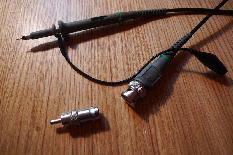
A first thing you want to buy, if you want to work on synthesizers, is a female BNC to male cinch adapter plug. This way you can plug your probe in an audio mixer or amplifier. This is most useful as there is no better measurement instrument than your ears when it comes to audio. Use this for poking around on various testpoints to follow the signal and to hear where it goes wrong.
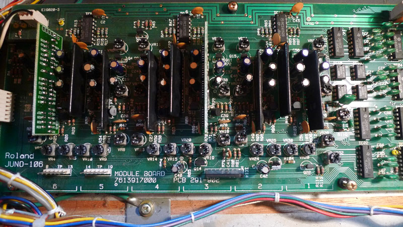
There are numbers on the bottom of the JUNO-106 module board from 1 to 6: These show where the electronics of each voice are.
There are numerous testpoints on the JUNO-106's pcb's. The most interesting are TP19-TP14 (yes, reverse order) which are the outputs of the VCF's for voice 1-6 and TP8-TP13 which are the outputs of the VCA's for voice 1-6. Too bad they did not include testpoints for the output of the wave generators...
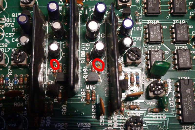
You can use the cathode (ring side) of D6-D1 (reverse order again, yes) as testpoints for the outputs of the wave generator circuits.
By probing on these testpoints you can know where it goes wrong. 99.9% chance that the problem will be solved by replacing the MC5534A of the voice where you see/hear problems on the testpoints for the wave generator circuits and replacing the 80017A of the voice where you see/hear problems on the testpoints for VCA and/or VCF. However, problems with the control voltages these hybrids need are also possible. Measure these too. See bottom of page 13 of the JUNO-106 service manual for the sample and hold circuits which generate these CV's. Also, do check them further upward after the resistors and capacitors in the circuit. Bad capacitors can also cause trouble.
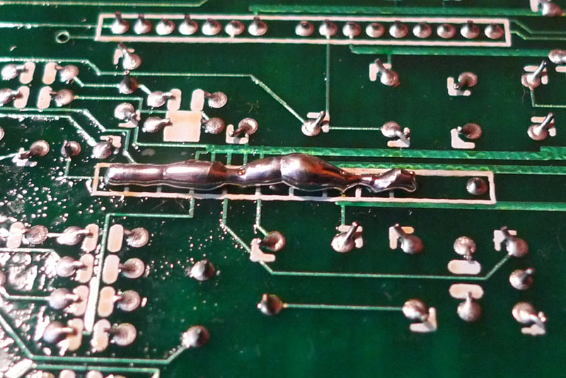
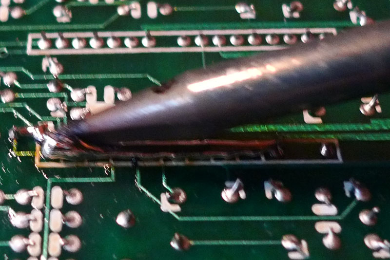
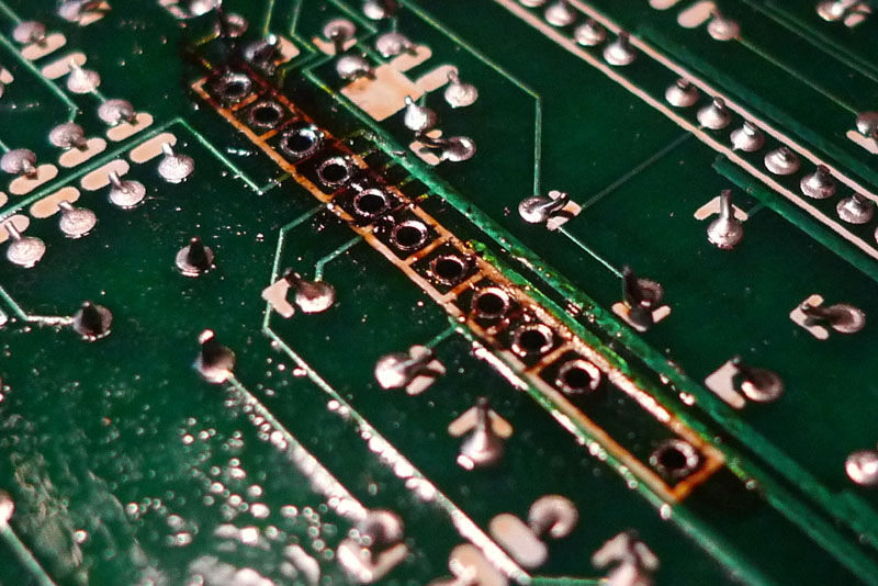
The most easy way to desolder one of these hybrid chips, is by adding a lot of solder to them...
Then slide your soldering iron back an forth over all the pins and when all the solder is molten: pull the chip out. Trying to desolder one pin at a time with vacuum solder or desolder wick is very hard.
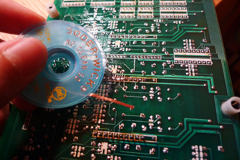
Then remove the excessive solder with desolder wick (The no-clean ones made by Chemtronics and Spirig are very good) or a vacuum solder. Whichever you like most.
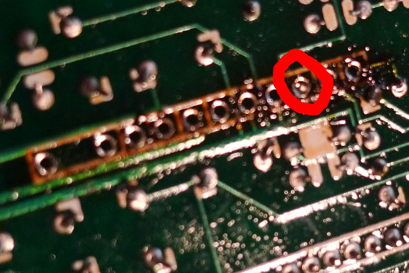
Sometimes solder keeps stuck in one of the holes and can not be removed with solder wick.
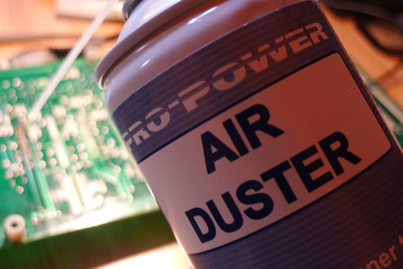
I use an air duster can to propel the solder out of the hole. Do not forget to clean up the solder that sprayed onto the pcb out of the hole.
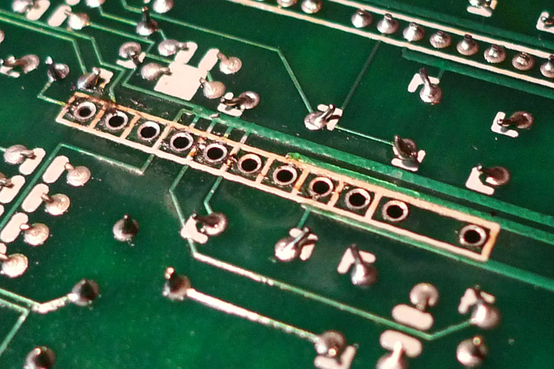
After you are done desoldering, you will have left a brown gooey flux mess. Depending on which kind of solder and desoldering wick you use, this flux residue can be conductive enough to deteriorate the performance of your JUNO-106...
Clean it up with flux remover...
Now the board is ready to insert a new chip. When this is done, you will need (not when replacing only an MC5534A) to do the adjustment procedure which is described in the JUNO-106 service manual.